










Description
24 kV 250A Deadbreak Straight Receptacle - Type A Interface for Underground Cable Terminations
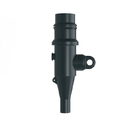
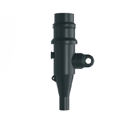
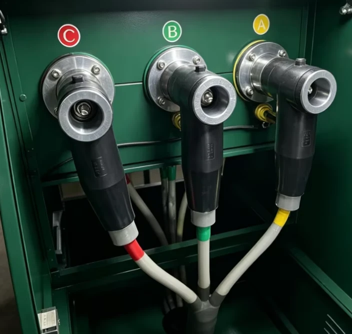
The 24 kV 250A deadbreak straight receptacle is a fully shielded and insulated termination for connecting underground cable to transformers, switchgear and other apparatus equipped with deadbreak bushings, junctions or other deadbreak connectors. It is an in-line ("straight") termination: the cable enters one end and the Type A 250A separable interface is presented at the other, with no tee branch.
The receptacle meets all the requirements of EN 50180, EN 50181 and IEC 60502, and is designed to be fully interchangeable with competitor products and mating products that meet EN 50180 / EN 50181.
What "straight receptacle" means
In a separable MV system the connector form follows the joint it has to make:
a T-body connector makes a tee - cable in, apparatus up, arrester or plug on the back.
a straight receptacle makes a straight, in-line joint - cable in at one end, deadbreak interface out at the other.
The straight form suits points where the cable runs straight into the apparatus and no branching is needed. It is the compact, single-motion option for terminating underground cable onto deadbreak bushings, junctions and deadbreak connectors, and - being fully shielded - it keeps the joint dead-front and touch-safe.
Built to be interchangeable
Interchangeability is the point of the EN 50180 / EN 50181 interface, and this receptacle is engineered for it:
Meets EN 50180, EN 50181 and IEC 60502.
Fully interchangeable with competitor products and with any mating product meeting EN 50180 / EN 50181.
Bi-metal compression connector as standard (for copper and aluminium conductors), with an optional copper connector for copper-only applications - so one receptacle body serves both common conductor types.
Voltage and short-circuit performance
| Parameter | Value |
|---|---|
| Voltage class | 24 kV |
| AC withstand, 5 minute | 54 kV |
| BIL and full-wave crest | 125 kV |
| Partial-discharge minimum extinction voltage | 20 kV |
| Thermal short circuit (conductor, 2 sec) | 23 kA / 2 s |
| Dynamic short circuit (conductor, 10 sec) | 82 kA / 10 ms |
| Screen leakage current | ≤ 0.5 mA |
Production tests follow IEC 60502. The ≤ 0.5 mA screen leakage current confirms the shield and drain path are sound - the marker of a properly screened, dead-front joint.
Construction
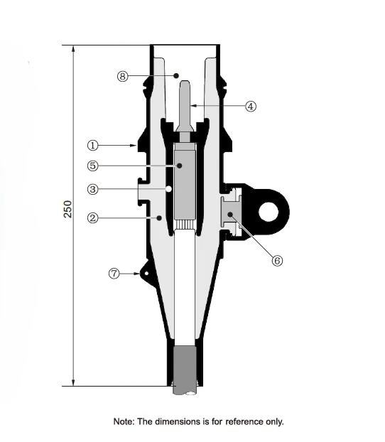
Semiconducting shield - precision-moulded, peroxide-cured semiconducting shield provides ground-shield continuity and meets the requirements of IEEE Standard 592.
Insulation layer - high-quality peroxide-cured EPDM, mixed and formulated in-house for complete control of the rubber characteristics.
Semiconducting insert - precision-moulded, peroxide-cured semiconducting insert provides corona-free electrostatic shielding of the compression connector.
Pin probe - a tin-plated copper probe that allows dependable switching operations.
Compression connector - standard Bi-metal, or optional Copper, compression connector, sized to ensure a cool-running connection with maximum current transfer.
Capacitive test point - a capacitive test point on the moulded body with a snap-on cap, giving a shielded, hot-stick-operable means to determine circuit condition.
Drain wire tab - provides a convenient point to connect the drain wire and ensure grounding of the connector shield.
Operating interface - Type A, 250A interface as described by EN 50180 and EN 50181.
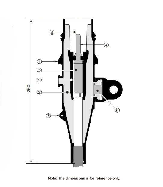
Cable range and conductor selection
The receptacle covers cable insulation diameters from 16.0 mm to 33.5 mm (six range codes) and conductor sizes from 25 mm² to 120 mm² (seven conductor codes).
Cable range codes (by cable insulation outer diameter)
| Cable range code | Inches | Millimetres |
|---|---|---|
| A | 0.630–0.820 | 16.0–20.8 |
| B | 0.700–0.920 | 17.8–23.1 |
| C | 0.830–1.100 | 21.6–27.9 |
| F | 0.770–0.950 | 19.6–24.1 |
| H | 0.929–1.039 | 23.6–26.4 |
| J | 1.098–1.318 | 27.9–33.5 |
Conductor codes
| Conductor code | AWG or kcmil | mm² |
|---|---|---|
| 01 | 3 | 25 |
| 02 | 2 | 35 |
| 03 | 1/0 | 50 |
| 04 | 2/0 | 70 |
| 05 | 3/0 | 95 |
| 06 | 4/0 | - |
| 07 | 250 | 120 |
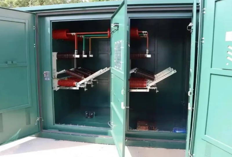
The kit
Each straight kit is supplied in a heavy-duty polyethylene bag and contains:
Standard straight receptacle body
Bi-metal or copper compression connector
Drag hook (M4)
Dished nut
Stainless steel bail assembly
Silicone lubricant
Installation instruction sheet
Clean paper
Where the straight receptacle is used
Underground cable to transformers
Where an underground MV cable rises into a transformer fitted with a deadbreak bushing, the straight receptacle terminates the cable and mates straight onto the bushing - a compact, screened joint with no tee and no branching. A common point in pad-mounted and compact substations.
Underground cable to switchgear
Connecting cable into switchgear equipped with deadbreak bushings or junctions, where the cable approaches in-line and the straight form gives the cleanest, lowest-profile termination.
Apparatus fitted with deadbreak bushings, junctions or deadbreak connectors
The receptacle is designed as a general mating termination for any apparatus that presents a conforming deadbreak interface - bushings, junctions or other deadbreak connectors - so one part covers a range of deadbreak connection points.
Cable-jointing and maintenance work
Because it is fully shielded, dead-front and intermateable, the receptacle is suited to jointing and maintenance programmes where replaced or newly pulled cable must connect to existing EN 50180 / EN 50181 apparatus without adapters.
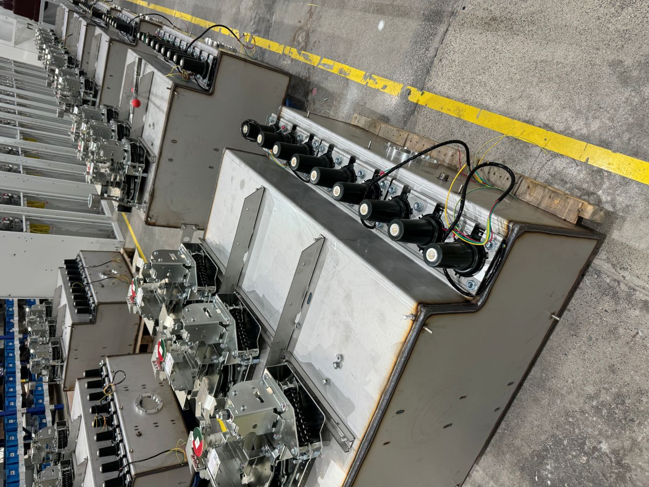
Product display


Send us your cable insulation diameter, conductor size and material, the apparatus interface you are mating to, and whether you need the copper connector option - we will confirm the correct range/conductor codes and quote the kit.

FAQ
Q. What is a deadbreak straight receptacle?
A fully shielded, insulated cable termination whose separable interface runs straight (in-line) - cable in at one end, deadbreak interface out at the other - used to connect underground cable to apparatus fitted with deadbreak bushings, junctions or deadbreak connectors.
Q. How is it different from a T-body connector?
A T-body connector makes a tee (cable + apparatus + rear leg); a straight receptacle makes an in-line joint. They also differ by current class here: this receptacle is 250A (Type A), the T-body family is 630A (Type C).
Q. Which interface does it present? A Type A, 250A separable interface per CENELEC EN 50180 / EN 50181.
Q. Is it interchangeable with other makes?
Yes - it meets EN 50180, EN 50181 and IEC 60502 and is fully interchangeable with competitor products and mating products meeting EN 50180 / EN 50181.
Q. Does it have a test point?
Yes - a capacitive test point with a snap-on cap, shielded and hot-stick operable, to determine circuit condition.
Q. What is the pin probe for?
The tin-plated copper pin probe allows dependable switching operations.
Q. What conductor types are supported?
A Bi-metal compression connector is standard (for copper and aluminium conductors); an optional copper connector covers copper-only applications.
Q. What cable sizes fit?
Cable insulation diameters from 16.0 mm to 33.5 mm (range codes A–J) and conductors from 25 mm² to 120 mm² (codes 01–07).
Q. What short-circuit and screen performance is specified?
Thermal short circuit 23 kA / 2 s, dynamic short circuit 82 kA / 10 ms, and screen leakage current ≤ 0.5 mA.
Q. What standard is it tested to (24kV receptacle EN 50180 / IEC 60502)?
Production tests follow IEC 60502; the interface conforms to EN 50180 / EN 50181.
Hot Tags: 24kv 250a deadbreak straight receptacle, China 24kv 250a deadbreak straight receptacle suppliers, transformer access points, transformer inverters, transformer prices, transformer radio frequency accessories, transformer server room accessories, transformer shafts