







Description
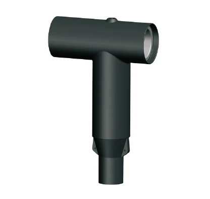
24 kV Front T-Body Connector - 630 A Separable Connector for 20 kV & 24 kV Distribution
Doubling a network's voltage roughly doubles the dielectric duty its cable accessories must survive - and that is the whole design brief for this connector. This is a 24 kV class, 630 A separable T-body, rated to a 125 kV basic impulse level (BIL), a 54 kV AC withstand and a 20 kV partial-discharge extinction voltage. It terminates XLPE or EPR cable into the dead-front bushings of transformers, switchgear and ring main units (RMUs) on 20 kV and 24 kV systems, and because it is separable, the joint can be broken and re-made without cutting the cable.
If you are specifying a 12 kV network, a lighter connector will do; the interesting engineering question here is what changes when the system voltage doubles.
Insulation Coordination: 24 kV Is a Different Duty
The single most misleading assumption in this product family is that a 24 kV connector is a 12 kV connector "with a bigger number on the box". It is not. A 24 kV separable connector is a re-dimensioned dielectric system:
Impulse withstand rises to 125 kV BIL - the level a 24 kV network's switching and lightning surges demand, coordinated to sit below the withstand of the apparatus the connector feeds.
Power-frequency withstand rises to 54 kV (5 min, 60 Hz, crest).
Partial-discharge extinction voltage rises to 20 kV - a higher PD threshold means the connector stays discharge-free with a wider operating margin above system voltage, which is what limits long-term insulation ageing.
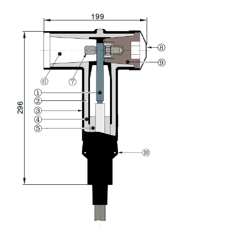
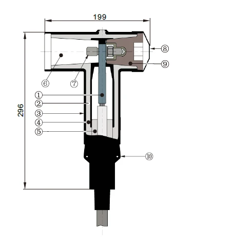
The insulation wall, creepage path and overall body grow with the voltage - the 24 kV body measures 199 mm × 296 mm, larger than the 12 kV tier, because separation distances cannot simply be scaled by a factor.
Designed Around 20 kV and 24 kV Network Conventions
20 kV and 24 kV distribution is the backbone of many European, Middle Eastern, African and Asia-Pacific networks, where CENELEC separable-connector interfaces are the de-facto standard at ring main units, compact substations and cable-to-transformer connections. Because this connector uses the CENELEC Type C, 630 A interface, it lands on those standard dead-front bushings without an adapter and stays interchangeable with other compliant connectors - a 24 kV T-body connector for 20 kV networks does not need a bespoke bushing.
Inside the Body: Three Sub-Systems
Read at 24 kV it is clearer to describe the connector as three cooperating sub-systems, each stressed differently at the higher voltage, than as a flat component list.
1. The dielectric sub-system - carrying the electric field
Insulation: high-quality peroxide-cured EPDM, mixed and formulated in-house so its rubber characteristics are controlled end-to-end rather than bought in.
Semiconducting insert: a precision-molded, peroxide-cured insert forms a corona-free electrostatic screen around the compression connector - the point where the field would otherwise concentrate most sharply.
Semiconducting shield: a precision-molded, peroxide-cured shield restores ground-shield continuity across the connector so the screen never "opens" at the joint.
2. The current-carrying sub-system
Compression lug: bi-metal as standard (works on copper and aluminium), plated copper as an option (copper only); sized to run cool at maximum transfer current.
Stud: zinc-plated threaded steel stud tying the body to the apparatus bushing.
3. The interface, plugging and earthing sub-system
Interface: Type C, 630 A, as described by CENELEC EN 50180 and EN 50181.
Insulating plug: molded epoxy plug selected for electrical, thermal and mechanical reliability.
Conductive rubber cap: completes the grounding system.
Drain wire tab: a dedicated bonding point for the drain / shield wire.
Cable adapter: molded adapter that fits the cable and provides stress relief at the screen cut - sized for 17.2–35 mm insulation diameter.
Cable Compatibility: A Tighter, A–G Window
Thicker 24 kV cable insulation means tighter adapter steps, so the usable window is narrower than on the 12 kV connector: 17.2 mm to 35 mm insulation diameter (0.677–1.378 in), covered by range codes A through G. Measure the cable's insulation diameter - not the conductor and not the overall diameter - and choose the range code before ordering.
| Cable range code | Inches | Millimetres |
|---|---|---|
| A | 0.677–0.807 | 17.2–20.5 |
| B | 0.717–0.846 | 18.2–21.5 |
| C | 0.815–0.945 | 20.7–24.0 |
| D | 0.933–1.063 | 23.7–27.0 |
| E | 0.992–1.122 | 25.2–28.5 |
| F | 1.130–1.260 | 28.7–32.0 |
| G | 1.248–1.378 | 31.7–35.0 |
parameters
| Group | Parameter | Value |
|---|---|---|
| Dielectric | Voltage class | 24 kV |
| Impulse withstand (BIL / full-wave crest) | 125 kV | |
| AC withstand, 5 min (60 Hz, crest) | 54 kV | |
| Partial-discharge minimum extinction voltage | 20 kV | |
| Current | Thermal short circuit (conductor, 2 s) | 23 kA / 2 s |
| Dynamic short circuit (conductor, 10 s) | 82 kA / 10 ms | |
| Screen leakage current | ≤ 0.5 mA | |
| Conductor range | 25–300 mm² | |
| Interface | Type | CENELEC Type C, 630 A |
| Standards | EN 50180 / EN 50181 | |
| Materials | Insulation | Peroxide-cured EPDM (in-house formulated) |
| Semiconducting components | Molded peroxide-cured insert + shield | |
| Mechanical | Nominal dimensions | 199 mm × 296 mm |
| Compliance | Test standard | IEC 60502-4 |
Product display


The Complete Kit
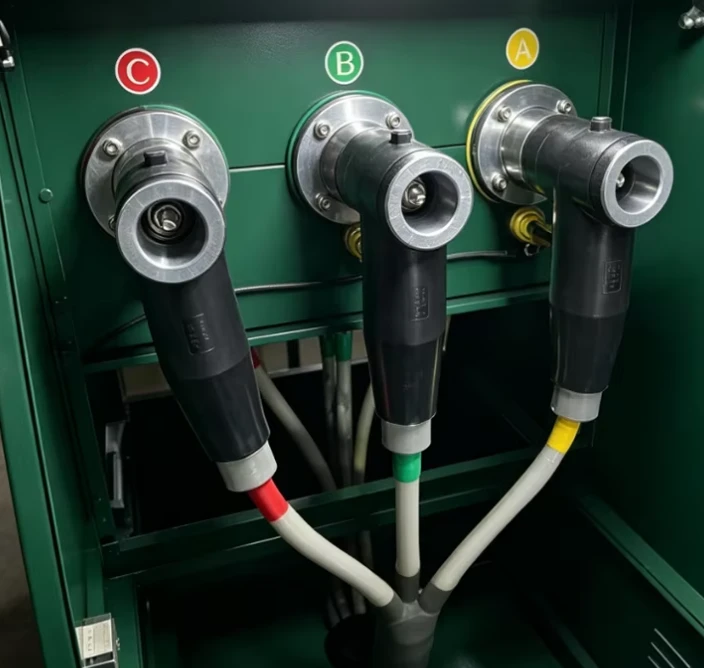
Supplied in a heavy-duty polyethylene bag, one 24 kV front T-body kit contains: the standard front T-body; a bi-metal compression lug (copper lug optional); stud with hex nut, washer and spring washer; an insulating plug with conductive rubber cap; a molded cable adapter; silicone lubricant; an installation instruction sheet; and a clean paper wipe.
Lug rule: choose bi-metal for copper and aluminium conductors; choose copper only for copper. On European 20 kV systems with aluminium cable, bi-metal is usually the correct specification.
Applications
1. Ring main units on 20 kV and 24 kV networks
In CENELEC-style ring networks the RMU is the standard node, and its separable bushings are the natural home for a 24 kV T-body. The connector lets a cable section be swapped or a faulted leg isolated without cutting the cable - the reason separable connectors, not taped joints, define these networks.
2. Transformer connections on higher-voltage feeders
At the transformer end, the dead-front bushing sees the full surge environment of the feeder. A 24 kV-rated body with 125 kV BIL and 20 kV PD extinction keeps the transformer interface insulated to the same class as the transformer itself, rather than introducing a weak link at the connector.
3. Industrial and process plants on 20 kV distribution
Large plants that distribute power at 20 kV - heavy industry, mining, chemical and water treatment - typically run long internal cable routes and their own switching stations. The separable, re-enterable design suits plants that reconfigure loads often, and the higher PD margin copes with the longer connected cable lengths.
4. Compact and pad-mounted substations
The fully screened, dead-front body removes exposed live parts, which is what lets a compact substation keep a small footprint. Even though the 24 kV body is physically larger than the 12 kV tier, it is still a plug-in module mounted directly on the bushing.
5. Overhead-to-underground transitions on 20 kV feeders
Where an overhead feeder transitions to underground cable, surge exposure is highest. A 24 kV separable connector at the transition, with the apparatus' own arrester protection, keeps the cable end insulated to class right at the point where surges are most likely to arrive.
6. Renewable and critical-infrastructure feeders at 20 kV / 24 kV
Wind, solar and data-centre projects that collect power at 20 kV or 24 kV lean on separable connectors for maintainable, re-enterable terminations. The higher PD extinction voltage and 125 kV BIL help protect the more surge-sensitive electronics at the far end of the collection network.

FAQ
Q1. What is a 24 kV front T-body connector?
A 24 kV front T-body connector is a fully screened, separable tee connector that terminates a medium-voltage polymeric cable into dead-front apparatus (transformer, switchgear or RMU) on 20 kV or 24 kV networks. "Front" refers to the front T-body (DFT) that makes the apparatus connection.
Q2. What interface does it use (24 kV T-body connector EN 50180 / EN 50181)?
It uses the CENELEC Type C, 630 A interface described by EN 50180 and EN 50181, so it mates directly with standard Type C dead-front apparatus bushings.
Q3. Can it terminate XLPE cable?
Yes - it terminates all polymeric cable types, including XLPE and EPR, over cable insulation diameters of 17.2–35 mm.
Q4. Can it be used with aluminium conductors?
Yes - specify the standard bi-metal compression lug, which suits both copper and aluminium conductors. The copper lug is for copper conductors only.
Q5. What standard is it tested to (IEC 60502-4 24 kV T-body connector)?
Production tests are conducted to IEC 60502-4, with a 54 kV AC withstand (5 min, 60 Hz crest), a 125 kV BIL and a 20 kV partial-discharge minimum extinction voltage.
Q6. What cable and conductor sizes does it cover?
Cable insulation diameters from 17.2 mm to 35 mm (0.677–1.378 in) and conductor sizes from 25 mm² to 300 mm².
Q7. Is it suitable for indoor and outdoor use?
Yes. The 24 kV front T-body connector is designed for both indoor and outdoor 20 kV / 24 kV applications.
Hot Tags: 12kv t-body connector, China 12kv t-body connector suppliers, transformer attenuators, transformer building automation accessories, transformer hubs, transformer industrial automation accessories, transformer it infrastructure accessories, transformer quotations