


Core Knowledge & Essential Terms of High/Low-Voltage Switchgear
Introduction
High and low-voltage switchgear assemblies are integrated electrical systems that combine power distribution, control, protection, and measurement equipment. They serve as the "nerve center" of power systems, ensuring safe, stable, and efficient operation. Below is a systematic collation of key foundational knowledge, professional terminology, and core principles-optimized for B2B international trade and independent station content.
1. Fundamental Definitions & Core Concepts
What does "Complete Set (Integrated)" Mean?
Switchgear is called "complete set" because it integrates multiple functional units (inlet, metering, PT, outlet, etc.) and pre-installs primary/secondary components that must work together as a system. It is a pre-assembled, turnkey solution rather than individual standalone equipment.
Key Voltage Grades in China & Their Purpose
表格
| Voltage Grade | Application Scenario | Core Role |
|---|---|---|
| 500kV / 220kV / 110kV | Long-distance power transmission | Reduce line loss; High voltage = lower loss for long-distance transport |
| 35kV / 10kV | Industrial parks, commercial buildings, power distribution stations | Regional power distribution |
| 380V / 220V | End-user equipment (motors, lighting, household appliances) | Final power supply |

2. Core Safety & Operational Principles
Why is Discharge Required for 10kV Systems?
During power outages, capacitors and circuits retain residual voltage. Discharging is mandatory to prevent electric shock hazards for maintenance personnel.
Safe Discharge Procedure (10kV)
Do not touch the busbar directly when opening the cabinet door.
Use a 10kV voltage tester to check for live current first.
Connect one end of a grounding wire to the ground and the other end to the tip of the voltage tester.
Use the tester tip to contact the busbar for discharge.
Complete discharge before maintenance to ensure personal safety.
Standard Withstand Voltages for 10kV Testing
| Standard | Test Voltage (Cabinet) | Test Voltage (Break Port) |
|---|---|---|
| Domestic (GB) | 42kV | 48kV |
| International (IEC) | 36kV | 36kV |
Function of Pressure Relief Channels
In case of cabinet explosion, high-pressure gas surges are generated. Pressure relief channels (on top of the cabinet) direct gas outward to prevent damage to other components. Without them, gas will burst through the weakest point, causing widespread failure.
Air Insulation Distance (National Standard)
For 10kV systems: 125mm minimum clearance between phases and to ground.
Insulation Creepage Distance
The surface leakage distance (along the insulator surface) between high-voltage live parts and ground. For 10kV: 235mm minimum.
3. Primary & Secondary Components (Key Equipment)
Primary Components (Main Power Loop)
| Component | Function | Application Scenario |
|---|---|---|
| Circuit Breaker | Load switching, overcurrent/short-circuit protection; Vacuum/SF6 types | 10kV/35kV/110kV systems |
| Disconnector | Isolates power with a visible break; No load operation | Fixed-type cabinets |
| Lightning Arrester | Absorbs overvoltage to protect equipment from surges | Every cabinet (inlet/outlet) |
| Current Transformer (CT) | Measures/meters current; Provides protection signals | 10kV+ systems |
| Voltage Transformer (PT) | Measures/meters voltage; Supplies power for protection/control | 10kV+ systems |
| Zero-Sequence Transformer | Detects unbalanced current for ground fault protection | 10kV+ systems |
| High-Voltage Fuse | Protects transformers (including PTs) | Transformer circuits |
| Earthing Switch | Grounds live parts during maintenance; Prevents back-feeding | Outlet terminals |
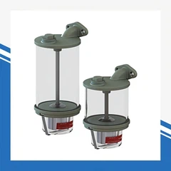
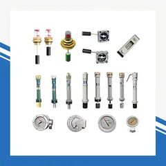
| Live Indicator | Visual indication of live status inside the cabinet | All live sections |
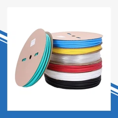
| Busbar | Conducts main power; Insulated sleeves reduce air clearance risk | Main power loop |
Secondary Components (Control/Protection Loop)
| Component | Function |
|---|---|
| Contactor | Remote control of motor/load switching |
| Relay | Protection logic (overvoltage, undervoltage, overcurrent) |
| Program Lock | Interlocks cabinet operation sequence; Prevents misoperation |
| Temperature/Humidity Controller (Wet Controller) | Monitors humidity; Activates heating to prevent condensation |
| AC/DC | AC (Alternating Current) = Main power supply; DC (Direct Current) = Control/auxiliary power |
Core Component Principles
Vacuum Circuit Breaker
Uses a vacuum interrupter (vacuum degree < 10⁻⁴ Pa) as the arc extinction medium.
Suitable for 10kV/35KV voltage grades; Reliable, low maintenance.
SF₆ Circuit Breaker
Uses SF₆ gas for arc extinction; 10x higher breaking capacity than standard breakers.
Advantages: Low arc voltage, short arcing time, low contact wear.
Disadvantages: High cost; Requires gas recovery; Complex structure.
Application: 220kV+ ultra-high voltage systems; Compact, space-saving.
Current Transformer (CT)
Series-connected with the load; Step-down current for metering/protection.
Ratio: I1N1=I2N2 (Current is inversely proportional to turns ratio).
Never open the secondary side during operation (risk of high voltage).
Voltage Transformer (PT)
Parallel-connected with the load; Steps down voltage for measurement/protection.
Ratio: U1/U2=N1/N2 (Voltage is proportional to turns ratio).
Never short the secondary side during operation.
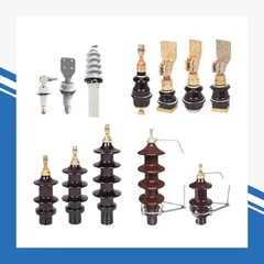
High-Voltage Insulator
Supports/fixes live conductors; Ensures insulation between conductors and ground.
Surface design (corrugated skirts) increases creepage distance to prevent flashover.

4. Critical Operational Accessories & Mechanisms
Live Door (Baffle)
Closes the live static contact when the handcart is withdrawn.
Prevents accidental contact with high voltage during maintenance.
Program Lock
Enforces operational sequence interlocks between cabinets.
Prevents human error (e.g., closing a breaker before isolation).
Lightning Arrester (Key Role)
Function: Absorbs overvoltage (lightning/switching surges) to protect equipment.
Mandatory Installation: Every cabinet (inlet/outlet) to ensure safety.
Inlet cabinet: Protects internal lines from external surges.
Outlet cabinet: Protects against overvoltage from vacuum breaker switching.
Wet Controller (Humidity Controller)
Detects humidity via a sensor; Activates heating elements to regulate moisture.
Modes: Automatic (auto-adjust) / Manual (manual control).
Prevents condensation, insulation degradation, and short circuits.
5. Diagrams & System Basics
Single-Line Diagram (Primary Scheme Diagram)
Represents the main power loop (primary components) and their wiring/connection topology.
Core elements: Busbars, transformers, breakers, disconnectors, CT/PT, fuses.
Power Transformer Basics
Converts voltage/current (does not change power).
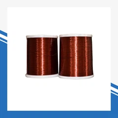
Core structure: Closed silicon steel core (0.35-0.5mm thick) + two insulated windings (primary/secondary).
Three-phase transformers: Three single-phase units connected in a group.

6. Common Technical Q&As (B2B FAQ Section)
Q: Can CTs be installed in reverse?
A: No. The standard current flow is L1 → L2. Reversing (L2 → L1) requires modification of the secondary wiring design to avoid incorrect measurement/protection signals.
Q: How to check vacuum degree in a vacuum switch?
A: Perform a withstand voltage test at 48kV for the break port. A 合格 (qualified) vacuum switch will withstand the test without breakdown.
Q: What is the role of a ring main unit (RMU)?
A: Enables load-breaking switching; Protected by high-voltage fuses for transformers. Widely used in distribution networks.
Q: Why insulate busbars with sleeves?
A: Reduces required air insulation distance; Prevents short circuits caused by small animals (rodents, insects) entering the cabinet.
7. Key Terminology Glossary (English-Chinese)
| English Term | Core Definition | |
|---|---|---|
| High/Low-Voltage Switchgear | Integrated power distribution/control systems | |
| Switchgear Cabinet | Main power distribution cabinet | |
| Circuit Breaker | Load switching + overcurrent protection | |
| Disconnector | Visible isolation (no load) | |
| Lightning Arrester | Overvoltage absorption | |
| Current Transformer (CT) | Current measurement/protection | |
| Voltage Transformer (PT) | Voltage measurement/protection | |
| Vacuum Interrupter | Arc extinction in vacuum breakers | |
| SF₆ Gas | Insulation/arc extinction medium | |
| Pressure Relief Channel | Explosion gas exhaust | |
| Creepage Distance | Insulator surface leakage distance | |
| Live Indicator | Live status indication | |
| Earthing Switch | Safety grounding during maintenance | |
| Program Lock | Misoperation prevention |