










The grid-edge workhorse

Distribution transformers step 10 kV and 20 kV down to 0.4 kV for the end customer. They are installed in enormous numbers and often run at modest load factor, which is why a small per-unit loss saving compounds into a very large system-wide energy saving. Efficiency - not raw capacity - is the defining metric of this product.
One clarification before the comparison: "Distribution" describes the transformer's duty (the final step down to utilisation voltage). "Oil-immersed" and "dry-type" describe its construction. Our distribution line is oil-immersed (S13 / S20 / S22 / amorphous SBH22); dry-type distribution units are covered on our dry-type page.
Where distribution transformers are used
Utility & rural distribution - pole-mounted, pad-mounted and ground-mounted units feeding townships, villages and suburbs.
Box-type (compact) substations - the transformer inside a kiosk or prefabricated substation.
Industrial plants - LV supply for factories, workshops, mines and processing lines.
Buildings & public facilities - residential and commercial blocks, hospitals, schools, water treatment.
Renewables & storage - auxiliary and LV distribution at solar, wind and BESS sites.
New infrastructure - EV-charging hubs, telecom sites, and data-centre LV distribution.

Distribution vs oil-immersed vs dry-type - the differences
| Aspect | Oil-immersed distribution transformer (this page) | Dry-type transformer | Oil-immersed power transformer |
|---|---|---|---|
| Duty / role | MV (10/20 kV) → 0.4 kV, last-mile supply to end users | Same duty, indoors / at the load centre | Bulk HV/MV transformation, substation main |
| Insulating & cooling medium | Transformer oil + paper | Cast resin (solid) + air | Transformer oil + paper |
| Typical voltage | 10 / 20 kV → 0.4 kV | up to 35 kV → 0.4 kV | 35 / 110 / 220 kV |
| Typical capacity | 30 – 2,500 kVA | 30 – 3,150 kVA | 6.3 – 240 MVA |
| Fire safety | Oil-based - needs separation or outdoor siting | Fireproof, no oil | Oil-based - outdoor / fire-separated |
| Placement | Pole, pad, kiosk, substation | Indoor, at the load centre | Outdoor substation |
| First cost | Low | Higher | Highest |
| Maintenance | Periodic oil checks | Low / maintenance-free | Periodic oil checks |
| Best for | Utility & rural distribution, commercial, industrial LV | Buildings, load centres, oil-restricted sites | Transmission & substation main duty |

Parameter summary
Product range
| Parameter | Range / option |
|---|---|
| Series | S13 · S20 · S22 · S22-MR / S20-MR (fully sealed) · SBH22 (amorphous) |
| Rated capacity | 30 – 2,500 kVA |
| HV voltage | 10 / 10.5 / 11 kV; 20 kV |
| LV voltage | 0.4 kV |
| Tap changing | Off-circuit (NVTC), ±5 % / ±2 × 2.5 % |
| Vector group | Dyn11 / Yyn0 |
| Short-circuit impedance | ≈ 4 – 6 % |
| Cooling | ONAN |
| Core | Grain-oriented silicon steel / amorphous alloy |
| Standards | IEC 60076, GB 1094 |
Efficiency tiers
| Series | Character | Core |
|---|---|---|
| S13 | Mature, reliable and economical; meets the national S13 low-loss standard | Grain-oriented silicon steel |
| S20 / S22 | Progressively lower loss for tighter efficiency targets | Grain-oriented silicon steel |
| S22-MR / S20-MR | Fully sealed, maintenance-free; tidy, low-profile enclosure | Grain-oriented silicon steel |
| SBH22 | Lowest no-load loss; best for lightly loaded duty | Amorphous alloy |
Representative losses - S13-M, 10 kV class
| Capacity (kVA) | No-load loss (W) | Load loss (W) @75 °C, Dyn11 / Yyn0 | No-load current (%) | Impedance (%) |
|---|---|---|---|---|
| 100 | 150 | 1,580 / 1,500 | 1.6 | 4 |
| 200 | 240 | 2,730 / 2,600 | 1.3 | 4 |
| 400 | 410 | 4,520 / 4,300 | 1.0 | 4 |
| 630 | 570 | 6,200 | 0.9 | 4.5 |
| 1,000 | 830 | 10,300 | 0.7 | 4.5 |
| 1,600 | 1,170 | 14,500 | 0.6 | 4.5 |
| 2,500 | 1,610 | 21,000 | 0.4 | 4.5 |
Representative values; final figures are fixed per project.

The economics of no-load loss
No-load (core) loss is present 24 hours a day regardless of load, so in low-load-ratio duty - rural and township grids, and industrial sites running at roughly 50–80 % load factor - it dominates the lifetime energy bill. An amorphous-alloy core is easier to magnetise and demagnetise than conventional grain-oriented silicon steel. Against a traditional silicon-steel core, no-load loss can be reduced by roughly 80 %, and an amorphous unit draws about half the no-load loss of an S13-class transformer. Where a transformer will spend much of its life lightly loaded, that difference pays back year after year.
Core and coil design
Multi-step (5-step) mitered core in premium grain-oriented silicon steel to keep no-load current under control.
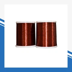
Compacted (flattened) winding conductor to increase contact area and raise winding mechanical strength.
No-pressure-ring assembly that keeps oil ducts clear and improves coil cooling.
Vacuum oil filling to stabilise insulation performance and extend service life.
Fully sealed (MR) construction on maintenance-free variants.
When do you need a distribution transformer?
You need one whenever power must be stepped from medium voltage (10 / 20 kV) down to the utilisation voltage (0.4 kV) at the point of use. Typical triggers:
New or extended LV supply - a substation or unit is being added to serve end users.
Utility / rural electrification - township, village or suburban distribution.
A commercial or residential development that takes MV supply and needs LV power.
An industrial plant requiring its own LV distribution.
A box-type or kiosk substation is being specified.
A renewable, BESS, telecom, EV or data-centre site needs LV distribution.
Replacement of an ageing or non-compliant unit with a higher-efficiency tier.
If the required voltage is above ~35 kV or the capacity above a few MVA, the duty belongs to a power transformer instead.


Market outlook - why demand keeps growing
Demand for distribution transformers is structurally strong, because they sit at the very edge of every electricity system:
Independent analysts put the global transformer market at roughly USD 70–81 billion in 2026, growing at about 6.5–8.8 % a year (Mordor Intelligence; Fortune Business Insights; MarketsandMarkets).
The distribution-transformer segment alone was valued at about USD 23.4 billion in 2026, projected to reach about USD 37.1 billion by 2033 (Persistence Market Research).
Drivers: electrification and load growth (urbanisation, industry, EV charging), renewable and storage integration, data-centre build-out, and the replacement of ageing grid fleets.
Efficiency regulation is accelerating the upgrade. In 2024 the U.S. Department of Energy finalised new energy-efficiency standards for distribution transformers, pushing the market toward higher-efficiency grain-oriented and amorphous cores.
What this means for buyers: lower-loss tiers (S20, S22 and amorphous SBH22) are taking a growing share of new orders, and total cost of ownership - not purchase price alone - now decides the specification.
Sources: Mordor Intelligence (2026); Fortune Business Insights (2026); MarketsandMarkets (2025); Persistence Market Research; U.S. Department of Energy (2024). Figures are third-party estimates and vary by scope.
Hot Tags: oil-immersed distribution transformers, China oil-immersed distribution transformers suppliers