










From alternating current to controllable direct current

From alternating current to controllable direct current
Industrial DC power is produced by a rectifier set - a rectifier transformer working with a rectifier cabinet. The transformer does two jobs in one unit:
It steps the grid-side high voltage down to a value matched to the required DC output.
It changes the phase number of the supply into the phase number the rectifier needs - 6, 12, 18, 24 or more phases.
The second job is what makes the rectifier transformer a specialist product: raising the secondary phase count is the primary lever for cutting harmonic distortion and improving power factor, and it is achieved entirely through the transformer's winding arrangement.
Pulse number & phase-shift configuration
The pulse number is the number of DC pulses produced per AC cycle, and it is set by how many phase-shifted secondary groups feed the rectifier. Each additional group adds another conduction path and cancels more of the low-order harmonics.
| Pulse number | Secondary groups | Phase displacement between adjacent groups | Dominant harmonic order (lowest remaining) |
|---|---|---|---|
| 6-pulse | 1 | 0° | 5th, 7th |
| 12-pulse | 2 (Δ + Y) | 30° | 11th, 13th |
| 18-pulse | 3 | 20° | 17th, 19th |
| 24-pulse | 4 | 15° | 23rd, 25th |
Phase-shift windings are the mechanism. A 12-pulse unit uses two secondaries - typically one delta and one star - giving the 30° displacement that makes the 5th and 7th harmonics cancel on the grid side. For higher pulse numbers, dedicated phase-shift (zig-zag) windings create the required displacement. Where separate transformers are operated in parallel, the same result is reached by giving each unit a defined phase-shift angle - for example a set of 0°, 7.5° and 15° displacements across combined units - so the harmonic cancellation happens at the point of common coupling.
The practical payoff


Grid-side harmonic currents drop sharply, reducing filtering duty downstream.
Power factor at the supply improves, cutting reactive-power penalties.
IEEE 519 and equivalent grid-code harmonic limits are met without excessive passive filtering.
DC output stays stable under load change, which is what the process actually needs.
Target industrial applications
Electrochemical industry - aluminium, magnesium, zinc, copper, chlor-alkali

Electrochemical industry - aluminium, magnesium, zinc, copper, chlor-alkali Non-ferrous electrowinning and electrorefining (aluminium, magnesium, zinc, copper) and the chlor-alkali process (caustic soda and chlorine production) all need very low DC voltage at extremely large DC current. This is the classic rectifier-transformer territory: high secondary current, high impedance, and a pulse number chosen to keep the enormous harmonic load off the grid.
Hydrogen generation systems
Water-electrolysis (green hydrogen) projects demand a rectifier supply that is highly stable and precisely controlled, because stack efficiency and membrane life depend on tight DC regulation. Our hydrogen rectifier transformers are specified around the stack's current ripple and control requirements.


Electroplating & surface treatment
Plating and anodising lines require smooth low-voltage, high-current DC to produce an even, defect-free deposit. Stable output - not raw power - is the specification that decides coating quality.
Traction substations & variable-speed drives
DC traction substations and large variable-speed drives use rectifier transformers to feed the converter that controls motors. Here the priorities are short-circuit withstand, immunity to cyclic loading, and reliable commutation.
Also supplied for: generator excitation · battery and capacitor charging · cascade (series) regulation · electrostatic precipitators (ESP) · general industrial DC power.

Special design features
Short-circuit and harmonic withstand
A rectifier transformer lives with the harmonic-rich current produced by thyristor or diode conversion, and with the mechanical forces of commutation faults. Both the windings and the core are reinforced for it:
Winding conductors, spacers and clamping are dimensioned for the additional mechanical stress imposed by non-sinusoidal current.
Core and winding losses are handled as harmonic losses, not only fundamental losses, so the thermal design accounts for the real heating.
High short-circuit impedance limits fault current and supports clean commutation.
Tap changing
Three routes are offered, selected to the process and the grid:
Off-circuit tap changing (OCTC / NVTC) - for stable supply voltage and a fixed process window.
On-load tap changing (OLTC) - for live voltage regulation where the grid or the process drifts.
Saturable reactor in combination with a tap changer - for fine, continuous output control where the electrolysis or drive process needs it.
Busbar and low-voltage terminals
On the secondary side, current - not voltage - rules the design. We use large-section copper busbar connections and a low-stray-impedance layout so that connections stay cool, losses at joints stay low, and the heavy DC current is delivered without local hot spots. Terminal and busbar arrangements are built to match the customer's rectifier cabinet interface.
Typical specification
| Parameter | Value |
|---|---|
| Rated capacity | 50 kVA – 20,000 kVA (custom) |
| Primary voltage | 10 kV / 20 kV / 33 kV (per system) |
| Secondary voltage & current | Customised, multi-stage output |
| Pulse number | 6-pulse / 12-pulse / 18-pulse / 24-pulse |
| Cooling method | ONAN / ONAF / OFAF |
| Impedance voltage | Project-specific (typically high, to limit fault current) |
| Vector group | Per pulse number and phase-shift arrangement |
| Product families | ZS / ZSSP (induction & general), ZHS (metallurgy & electrochemical) |
Two-winding and double-split (dual-secondary) units are available, optionally with an interphase reactor where the rectifier topology requires it.
System overview
Rectifier transformer in a typical industrial DC power system
HV Grid10·20·33 kV supply
01
RectifierTransformerphase-shift
02
RectifierCabinetthyristor / diode
03
DC bus→ load
04
Phase-shift windings cancel the lowest-order harmonics; displacement between adjacent secondary groups: 12-pulse = 30° | 18-pulse = 20° | 24-pulse = 15°
Rectifier transformer feeding a rectifier cabinet to supply an industrial DC load.
Testing & standards compliance
Rectifier transformers are designed and tested to the converter-transformer standards that overseas buyers audit against:
IEC 61378-1 - the dedicated standard for converter (rectifier) transformers.
IEC 60076 - power transformer general requirements.
IEEE C57.12.00 - general requirements for liquid-immersed distribution, power and regulating transformers.
GB 1094 series (where Chinese standards apply).
Before shipment, every unit passes a factory test programme that includes:
Ratio and connection-group (vector-group) test
No-load and load-loss measurement - including harmonic-loss measurement for a realistic loss figure under non-sinusoidal current
Impedance voltage / short-circuit impedance test
Temperature-rise test
Dielectric tests: insulation dielectric strength and induced withstand voltage
Lightning impulse withstand voltage test
A full routine and type-test report is issued with each transformer, giving documented evidence of performance.


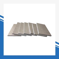
These slitting machines process steel coils to produce transformer core laminations.


FAQ
What is the difference between a standard power transformer and a rectifier transformer?
A standard power transformer delivers sinusoidal AC at the secondary. A rectifier transformer is designed to feed a rectifier, so it (a) provides the phase-shifted secondary groups (6/12/18/24-pulse) that cancel harmonics and improve power factor, (b) carries harmonic and large DC-side current loads, and (c) is built with reinforced windings, harmonic-aware thermal design and heavy-duty busbar terminals. It is also specified to IEC 61378-1 rather than only IEC 60076.
How do you determine the pulse number (6-pulse vs 12-pulse) required for my electrolysis system?
The pulse number is chosen from the grid-code harmonic limits the plant must meet and the size of the DC load. A small installation may be fine with 6-pulse; most electrochemical plants use 12-pulse or higher (18/24-pulse) to keep grid-side harmonics within IEEE 519 limits without excessive filtering. Share the DC voltage/current, the supply short-circuit capacity and the applicable harmonic standard, and we will recommend the correct configuration.
Can you customize the secondary DC voltage and current according to our rectifier cabinet specifications?
Yes - this is the normal way we build. Provide the rectifier cabinet's DC voltage and current, its pulse number and topology, and the grid conditions; we design the transformer's secondary voltage, tap scheme, impedance and busbar interface to match your cabinet exactly.
Do you supply the series/interphase reactor and test reports?
Yes. An interphase reactor or series reactor is supplied where the topology requires it, and full routine and type-test documentation is provided with every unit.
Hot Tags: rectifier transformers, China rectifier transformers suppliers