


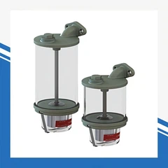
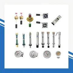




YZF-90~250 Series Oil Level Gauge
1. Outline Dimension Drawings of Oil Level Gauges
Code: TH.ZEA.012, Model: YZF1-140TH (with float)
Code: TH.ZEA.013, Model: YZF2-140TH (with floating ball)
Code: TH.ZEA.016, Model: YZF3-140TH
Code: TH.ZEA.014, Model: YZF2-200TH
Code: TH.ZEA.017 (Φ130), Model: YZF3-200TH
Code: TH.ZEA.018 (Φ135), Model: YZF3-200TH
Code: TH.ZEA.015, Model: YZF2-250TH
Code: TH.ZEA.013, Model: YZF2-140TH (with floating ball)

2. Electrical Wiring Diagram of Oil Level Gauge
The signal wiring method is shown in the figure below: Figure 1 is for three-wire terminals, and Figure 2 is for four-wire terminals. K1 and K2 are signal switches.
After connecting the oil level gauge, the junction box cover should be carefully reinstalled to prevent rainwater from seeping into the gauge body and affecting the normal use of the oil level gauge.
3. Selection & Ordering Instructions
When selecting the oil storage tank for the transformer, please refer to the figure below and select the corresponding oil level gauge and swing rod length (the distance from the center of the floating ball to the hinge point of the oil level gauge) to ensure the correctness of the oil level gauge's indication and the actual oil level.
(Applicable to open or switchable oil storage tanks, and capsule oil storage tanks)
4. Oil Level Gauge Installation Dimension Table
Outlet thread: M20×1.5
| Model | Flange outer diameter ΦD0 | Installation hole pitch circle ΦD | Specification of sealing gasket | Mounting Hole | Install flange opening |
|---|---|---|---|---|---|
| YZF1-90 | Φ90 | Φ75 | Φ60×Φ48×5 | 4-M8 | Φ44 |
| YZF1(2)-140 | Φ140 | Φ116 | Φ100×Φ90×5 | 4-M10 | Φ82 |
| YZF3-140 | Φ140 | Φ116 | Φ100×Φ90×5 | 4-M10 | Φ82 |
| YZF2-200 | Φ160 | Φ135 | Φ120×Φ106×7 | 6-M10 | Φ100 |
| YZF3-200 | Φ156 | Φ135 | Φ115×Φ105×5 | 6-M10 | Φ100 |
| YZF2-250 | Φ156 | Φ130 | Φ115×Φ105×5 | 6-M10 | Φ100 |
5. Oil Storage Tank Inner Diameter vs. Swing Rod Length
| Inner diameter of oil storage tank | YZF1-90 / YZF1-140 | YZF2-140 / YZF2-200 | YZF3-140 / YZF3-200 | YZF2-250 | Floating rod calculation formula |
|---|---|---|---|---|---|
| 310 | 120 | - | - | - | YZF1-90: L=D/2-45/2-10 |
| 330 | 130 | - | - | - | YZF1-140: L=D/2-80/2-10 |
| 440 | - | 170 | 330 | - | YZF2-140: L=D/2-80/2-10 |
| 500 | - | 200 | 420 | - | YZF2-200: L=D/2-80/2-10 |
| 600 | - | 250 | 560 | - | YZF3-140: - |
| 630 | - | 265 | 600 | 600 | YZF3-200: - |
| 800 | - | 350 | 840 | 840 | YZF2-250: L=1.414×(D/2-100) |
| 900 | - | - | 980 | - | - |
| 1000 | - | - | 1130 | - | - |
| 1100 | - | - | 1300 | - | - |
6. Installation Position & Swing Angle of the Floating Ball
| Model | Dial diameter (mm) | Pointer travel | Swing rod position at the lowest oil level | Swing angle of the swing rod | Installation position |
|---|---|---|---|---|---|
| YZF1-90 | Φ90 | 120° | 60° downward | 120° | Center of the oil storage tank wall |
| YZF1(2)-140 | Φ140 | 120° | 60° downward | 120° | Lower side of the oil storage tank wall |
| YZF3-140 | Φ140 | 270° | Horizontal | 45° | Lower side of the oil storage tank wall |
| YZF2-200 | Φ200 | 120° | 60° downward | 120° | Center of the oil storage tank wall |
| YZF3-200 | Φ200 | 270° | Horizontal | 45° | Lower side of the oil storage tank wall |
| YZF2-250 | Φ250 | 270° | Horizontal | 45° | Lower side of the oil storage tank wall |
Transformer Oil Level Gauges: Common Faults & Troubleshooting Guide
Oil level gauges are critical monitoring components for oil-immersed transformers. Below are the most common faults, their root causes, and step-by-step solutions, tailored to typical models like UHZ, YZF, and YW series gauges.
1. Pointer Not Moving / Stuck
This is the most common mechanical fault, which directly affects oil level monitoring accuracy.
Root Causes
Bent or deformed connecting rod/float arm
Debris, sludge, or scale inside the transformer tank jamming the float
Corrosion or wear on the internal magnetic coupling mechanism
Strong magnetic interference near magnetic-type gauges
Improper installation angle (not vertical) causing the float to bind
Solutions
Stop the transformer and isolate power before inspecting the gauge.
Remove the gauge body and check the connecting rod/float for bends or damage. Straighten or replace deformed parts.
Clean debris from the float and internal mechanism; flush the tank opening to remove sludge.
For magnetic coupling gauges, check for strong magnetic objects nearby and remove them.
Reinstall the gauge strictly vertically (within ±5° tolerance) to eliminate binding.
2. Pointer Stuck at High/Low Limit
The pointer remains fixed at the maximum or minimum position, failing to respond to oil level changes.
Root Causes
The float is stuck at the top/bottom of the tank due to tank deformation or obstructions
The gauge's internal stop pin is misaligned or damaged
Severe oil level deviation (e.g., severe leakage or overfilling) beyond the gauge's range
Mechanical wear causing the pointer spindle to seize
Solutions
Check the actual oil level using a reference method (e.g., dipstick) to rule out extreme oil shortage/overfill.
Remove the gauge and manually move the float to verify if it moves freely. If blocked, inspect the tank interior for obstructions.
Adjust or repair the gauge's internal stop pin if misaligned.
Lubricate the pointer spindle with transformer oil-compatible lubricant (for mechanical gauges).
3. Pointer Inaccurate / Erratic Readings
The displayed oil level does not match the actual oil level in the tank.
Root Causes
Temperature changes causing oil expansion/contraction (no correction applied)
Improper calibration of the gauge during installation
Wear of the magnetic coupling or transmission mechanism
Air bubbles trapped in the gauge body or tank
Leakage in the gauge's hermetic seal causing pressure imbalance
Solutions
Correct the reading for temperature: The gauge is calibrated at 25°C; adjust based on the actual oil temperature (oil expands with heat, contracts with cold).
Recalibrate the gauge using the transformer's known oil level as a reference.
Check for air bubbles: Vent the gauge (if equipped with a vent) or tap the gauge body gently to release trapped air.
Inspect the seal for leaks; replace damaged gaskets and re-seal the gauge.
4. Oil Leakage at the Gauge Connection
Oil seeps from the flange or threaded connection between the gauge and transformer tank.
Root Causes
Damaged or aged sealing gasket
Uneven bolt tightening on the flange
Warped flange or tank opening
Over-tightened threaded gauge causing thread damage
Solutions
Replace the sealing gasket with a new oil-resistant gasket (same material and size as the original).
For flange-mounted gauges, tighten the bolts evenly in a crisscross pattern to avoid warping the flange.
Check the flange/tank opening for warping; if severe, repair or replace the tank fitting.
For threaded gauges, apply a small amount of oil-compatible thread sealant and tighten to the manufacturer's recommended torque (do not over-tighten).
5. No Alarm Signal (For YZF/YW11 Series with Micro-Switches)
The high/low oil level alarm function fails to trigger when the oil level reaches the threshold.
Root Causes
Loose or damaged wiring connections
Misaligned micro-switch contacts
Burned-out micro-switch contacts due to excessive current
Incorrect wiring of the common/normally open/closed terminals
Solutions
Inspect the wiring connections at the gauge and control panel; tighten loose wires or replace damaged cables.
Check the micro-switch alignment and adjust the contact position to trigger at the correct oil level threshold.
Test the switch continuity with a multimeter; replace the micro-switch if burned out or faulty.
Verify the wiring matches the gauge's wiring diagram (common point, normally open/closed contacts).
6. Gauge Lens Fogging / Condensation
The transparent lens becomes fogged or covered in condensation, obscuring the pointer reading.
Root Causes
Moisture ingress through a damaged seal or loose lens
Temperature difference between the gauge interior and exterior
Poorly sealed gauge housing allowing humid air to enter
Solutions
Remove the lens and clean the interior with a dry, lint-free cloth.
Check the lens seal and replace it if damaged.
Re-seal the lens housing and ensure all seals are properly installed.
For persistent condensation, drill a small vent hole (if the gauge is designed for it) or install a desiccant pack inside the gauge housing (where applicable).
7. Corrosion on the Gauge Body/Components
Visible rust or corrosion on the gauge body, flange, or internal components.
Root Causes
Poor surface treatment or damaged protective coating
High humidity or corrosive environments (e.g., coastal substations)
Leakage of transformer oil (acidic byproducts) causing corrosion
Solutions
Clean corroded areas with a wire brush and apply anti-corrosion paint (compatible with the gauge material).
For severe corrosion, replace the corroded parts or the entire gauge to avoid structural failure.
Install a protective cover over the gauge to shield it from moisture and salt spray.
Inspect the transformer oil for acidity; if contaminated, perform oil treatment or replacement.
8. Common Troubleshooting Checklist
| Fault | Quick Checks | Immediate Action |
|---|---|---|
| Pointer stuck | Check if installation is vertical; inspect connecting rod for bends | Straighten/replace rod; re-install vertically |
| Leakage | Check gasket and bolt tightness | Replace gasket; tighten bolts evenly |
| No alarm | Verify wiring continuity; test micro-switch | Reconnect wires; adjust/replace switch |
| Fogging | Inspect lens seal; check for moisture ingress | Clean lens; re-seal housing |