








Understanding Three-Phase Power Transformers: Core, Windings, Tank, Conservator and More
Three-phase power transformers are the backbone of modern power transmission and distribution systems, enabling efficient voltage conversion to deliver electricity across grids, industrial facilities, and commercial buildings. For businesses in the electrical industry, understanding their core components and working principles is essential for product selection, operation, and maintenance. Below is a professional breakdown of the key parts of a three-phase oil-immersed power transformer, tailored for global trade and technical reference.
1. Core
The transformer core forms the magnetic circuit of the equipment, consisting of two main parts: core legs (core columns) and yokes.
Structure & Function: Coils (windings) are mounted on the core legs, while the yokes connect the legs to close the magnetic path, ensuring efficient magnetic flux transfer.
Material & Design: To minimize hysteresis and eddy current losses (the main sources of energy waste in transformers), the core is constructed from high-silicon electrical steel sheets (silicon steel laminations) with a thickness of 0.35–0.5 mm. Each lamination is coated with insulating varnish to isolate adjacent sheets and reduce eddy currents.
Core Types:
Core-type Transformer: Windings wrap around the core legs. This design features simple manufacturing processes and is widely used in power transformers.
Shell-type Transformer: The core wraps around the windings, offering better thermal conductivity and higher mechanical strength, but complex production limits its use to small power transformers only.

2. Windings (Coils)
Windings are the conductive parts of the transformer, responsible for carrying current and inducing electromagnetic induction. A three-phase transformer has two sets of windings:
High-Voltage (HV) Winding: Connected to the high-voltage side of the power grid, with more turns of thinner wire.
Low-Voltage (LV) Winding: Connected to the low-voltage side, with fewer turns of thicker wire.
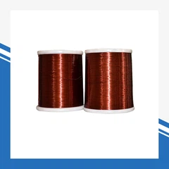
Key Features: Made of high-purity copper (or aluminum for cost-effective models) with Class F/H insulation, designed to withstand high voltage, current, and thermal stress during operation. The windings are tightly wound and insulated from the core and each other to prevent short circuits.
3. Tank & Outer Shell
The steel tank (outer shell) is the main body of the oil-immersed transformer, serving multiple critical functions:
It houses the core, windings, and insulating oil, protecting internal components from mechanical damage, dust, and moisture.
It acts as a heat sink, dissipating the heat generated by the core and windings during operation.
The tank is sealed to prevent oil leakage and maintain the insulating performance of the transformer oil.
4. Conservator (Oil Pillow / Oil Expansion Tank)
The conservator is a cylindrical oil storage tank mounted on top of the main transformer tank.
Core Function: Compensates for the volume change of transformer oil caused by temperature fluctuations. When the oil heats up and expands, excess oil flows into the conservator; when it cools and contracts, oil flows back into the main tank.
Additional Benefits: Reduces the contact area between transformer oil and air, slowing down oil aging and moisture absorption, and extends the service life of the transformer.
5. Other Critical Components
5.1 Nameplate
The nameplate is the "ID card" of the transformer, permanently marked with all key technical parameters, including rated capacity, voltage ratio, rated current, frequency, impedance voltage, cooling method, connection group, weight, and manufacturer information. It is essential for installation, operation, and maintenance.
5.2 Buchholz Relay (Gas Relay)
Installed between the main tank and the conservator, this is a core protective device for oil-immersed transformers.
It detects gas generated by internal faults (such as short circuits, insulation breakdown) or sudden oil level drops, triggering an alarm or automatic shutdown to prevent catastrophic failure.
5.3 Oil Level Gauge
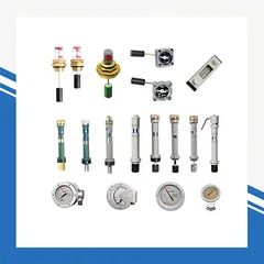
Mounted on the conservator, it visually displays the real-time oil level in the transformer, allowing operators to monitor oil volume and detect leaks or abnormal temperature conditions.
5.4 Temperature Indicator
Monitors the temperature of the top oil in the transformer tank and the winding temperature. It triggers an alarm when the temperature exceeds the safe threshold, preventing overheating damage to the insulation.
5.5 Breather (Moisture Absorber)
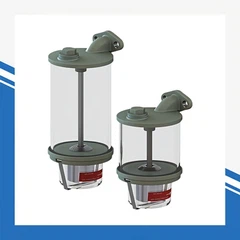
Connected to the conservator, it is filled with silica gel desiccant. It absorbs moisture from the air entering the conservator during oil volume changes, preventing moisture from contaminating the transformer oil and reducing insulation performance.
5.6 High & Low Voltage Bushings
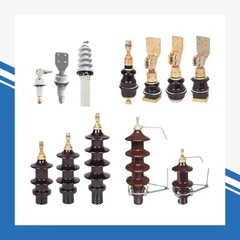
These insulated terminals pass through the tank wall, connecting the internal windings to the external power lines. They provide electrical insulation between the live conductors and the grounded tank, while withstanding high voltage and outdoor environmental conditions.
5.7 Tap Changer
Adjusts the turns ratio of the transformer to regulate the output voltage, compensating for voltage fluctuations in the power grid. It ensures the output voltage remains within the required range for end users.
5.8 Oil Drain Valve
Located at the bottom of the main tank, it is used for oil sampling, oil replacement, and maintenance of the transformer.
5.9 Safety Relief Vent ( Pressure Relief Device)
A protective device that releases high-pressure gas and oil from the tank in case of severe internal faults, preventing tank explosion and damage.
5.10 Truck & Grounding Bolt
The truck (rolling wheels) is installed at the bottom of the tank for easy transportation and installation of the transformer.
The grounding bolt is used to connect the transformer tank to the ground, ensuring electrical safety and preventing electric shock hazards.
Why This Matters for Your Business
For global buyers, engineers, and power system operators, a clear understanding of these components ensures:
Correct selection of transformers for specific power grid and application requirements
Safe and compliant installation, operation, and routine maintenance
Timely troubleshooting and fault diagnosis to minimize downtime
Compliance with international electrical standards (IEC, ANSI, etc.)
Whether you are sourcing power transformers for power plants, substations, industrial projects, or commercial buildings, mastering these core components is the first step to reliable and efficient power transmission.