
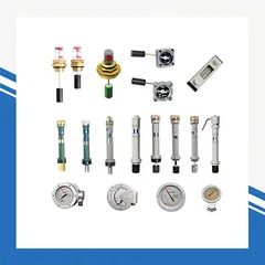


Transformer Pressure Relief Valve (YSF Series) – Industry Knowledge Guide
This guide details the parameters, purpose, performance, precautions, and usage of the YSF series pressure relief valves (0.03–0.06 MPa range), including both automatic and manual-release types.

1. Core Purpose & Performance
Purpose
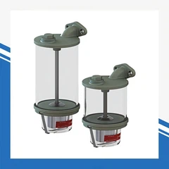
Pressure relief valves are critical safety components for oil-immersed transformers, capacitors, and other power equipment. Their primary function is to protect the tank from deformation or rupture caused by sudden internal pressure spikes during faults.
When an internal fault (e.g., winding overheating, arcing) occurs, transformer oil vaporizes, causing rapid pressure buildup inside the tank. The pressure relief valve automatically opens to vent excess gas, then closes tightly once pressure normalizes, preventing air/moisture from entering and contaminating the insulating oil.
Key Performance Features
Automatic Operation: Opens automatically when pressure exceeds the set value (0.03MPa or 0.06MPa) and closes when pressure drops below the threshold.
Manual Release Option: Equipped with a pull ring for manual pressure venting during maintenance or altitude changes.
Hermetic Sealing: The valve re-seals tightly after operation to prevent external air, water, and pollutants from entering the tank.
Environmental Resistance: Designed for use in temperatures from -35°C to 55°C, suitable for tropical and temperate climates.
2. Main Technical Parameters
| Parameter | Specification |
|---|---|
| Pressure Release Range | 0.03 MPa or 0.06 MPa (customizable) |
| Installation Thread | 1/4-18 NPT taper pipe thread (customizable) |
| Operating Temperature | -35°C ~ 55°C |
| Materials | Brass, 316 stainless steel, or carbon steel (corrosion-resistant options available) |
| Special Features | Rainproof cap, UV-resistant housing, anti-leakage design |
3. Key Structural Features & Their Functions
Base Recessed Design: Anti-UV coating slows aging, extending service life.
Valve Body Flared Nozzle: Facilitates smooth transformer oil backflow.
Dual Rainproof Structure: Withstands rainwater ingress, ideal for outdoor installations.
Waterproof Cover: Prevents rainwater from entering the valve body.
Locking Device: Prevents accidental opening during transportation and prevents oil spillage.
Pull Ring: Allows manual pressure venting, balancing internal/external pressure during altitude changes.
4. Usage & Installation Instructions
Step 1: Installation
Threaded Mounting: Install the valve using the 1/4-18 NPT thread. Apply PTFE tape or a sealing ring to the threads to ensure a tight seal.
Orientation: Mount the valve in a position where the discharged gas will not contact personnel, especially when the gas is at high temperature.
Safety Cap Removal: Remove the protective cap before commissioning (it is only for transportation protection).
Step 2: Operation
Automatic Operation: The valve will automatically open and close based on internal pressure, requiring no user intervention during normal operation.
Manual Venting:
Pull the ring in the direction of the arrow shown in the diagram.
Keep the pull rod aligned in a straight line during movement.
Release the ring slowly when resetting to avoid damaging the internal mechanism.
5. Critical Precautions
Sealing Check: Always ensure the valve is properly sealed after installation to prevent air leaks.
Environmental Limitations: Do not use the valve in environments with corrosive substances (e.g., rubber, copper) that may damage the materials.
Temperature Considerations: The valve must be installed away from high-temperature zones to avoid burns from vented gas.
Altitude Adjustment: Use the manual pull ring to release pressure when operating at high altitudes to prevent pressure imbalance.
Regular Inspection: Periodically check the valve for signs of damage, aging, or leakage, especially in harsh environments.
6. Common Troubleshooting
| Fault | Possible Cause | Solution |
|---|---|---|
| Valve fails to open during overpressure | Blocked nozzle, stuck internal parts, or incorrect pressure setting | Inspect and clear blockages; verify the pressure setting |
| Continuous oil leakage | Damaged seal, over-tightened threads, or a defective valve body | Replace the seal; check for thread damage; replace the valve if necessary |
| No automatic reset after operation | Debris stuck in the valve seat, or a weak return spring | Clean the valve seat; inspect and replace the spring |