


Whether you are an electrical engineer, project manager, or global buyer sourcing power distribution solutions, understanding the fundamentals of power system design, primary/secondary components, and wiring principles is critical for safe, reliable, and efficient electrical installations. This guide breaks down the core knowledge of power systems, primary/secondary electrical components, circuit schemes, and wiring practices, tailored for industrial, commercial, and utility applications.
1. Introduction to Power System Fundamentals
A power system is a network of electrical components designed to generate, transmit, distribute, and utilize electric energy. It forms the backbone of modern infrastructure, powering everything from industrial factories to commercial buildings and residential communities.
Core Functions: Power generation (power plants), high-voltage transmission (grid networks), medium/low-voltage distribution (substations), and end-user consumption.
Key Design Principles: Safety, reliability, efficiency, compliance with international standards (IEC, ANSI, NEC), and scalability for future expansion.
System Classification: Divided into primary systems (high-voltage power transmission/distribution) and secondary systems (control, protection, monitoring, and auxiliary circuits).
2. Introduction to Primary Electrical Components
Primary electrical components are the main power-carrying equipment that directly handles high-voltage, high-current power in the distribution system. They are responsible for power transmission, switching, protection, and voltage conversion.
Common Primary Components:
Power Transformers: Step up/down voltage for transmission and distribution (including oil-immersed and dry-type transformers).
High-Voltage Switchgear: Circuit breakers, load break switches, disconnectors, and fuse combinations for power control and fault protection.
Busbars: Conductive bars for centralized power distribution in switchgear and substations.
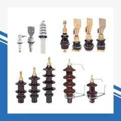
Surge Arresters: Protect equipment from lightning strikes and switching overvoltages.
Current/Voltage Transformers (CT/PT): Step down high current/voltage for measurement and protection.
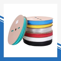
Cables & Bus Ducts: Insulated power transmission lines for indoor/outdoor distribution.
Reactors & Capacitors: For power factor correction, harmonic filtering, and fault current limitation.
3. Introduction to Primary Electrical Schemes
A primary electrical scheme is the overall design of the power distribution network, defining how primary components are connected to meet load requirements, safety standards, and operational needs.
Common Primary Scheme Types:
Radial Distribution Scheme: Simple, cost-effective, widely used in commercial and residential buildings.
Ring Main Unit (RMU) Scheme: High reliability, suitable for critical loads with dual power supply.
Dual Power Supply Scheme: Ensures uninterrupted power for mission-critical facilities (data centers, hospitals).
Substation Main & Standby Scheme: For industrial substations with high reliability requirements.
Generator Parallel Scheme: For on-site power generation and grid connection.
Key Design Considerations:
Load capacity and future expansion
Fault protection coordination
Power supply reliability
Compliance with local electrical codes
Maintenance accessibility
4. Introduction to Secondary Electrical Components
Secondary electrical components are low-voltage auxiliary equipment that controls, monitors, protects, and measures the primary power system. They do not directly carry high-voltage main power, but are essential for safe and automated operation.
Common Secondary Components:
Control & Protection Relays: Overcurrent relays, differential relays, voltage relays, and microprocessor-based protection relays.
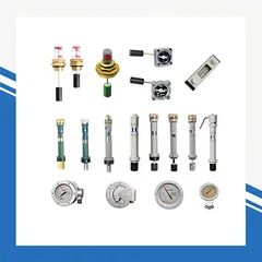
Metering & Monitoring Devices: Ammeters, voltmeters, power meters, energy meters, and SCADA remote monitoring units.
Control Switches & Buttons: For manual operation of circuit breakers and switches.
Indicator Lights & Alarms: For status indication and fault alerting.
PLC & Automation Controllers: For automated power system control and remote operation.
Auxiliary Relays & Contactors: For signal amplification and circuit control.
Wiring Terminals & Junction Boxes: For organized secondary circuit wiring.
5. Introduction to Secondary Circuit Principles
A secondary circuit is a low-voltage control, protection, and monitoring circuit that works with the primary power system. Its core function is to ensure the safe, reliable, and automated operation of the primary system.
Core Functions of Secondary Circuits:
Protection: Trigger circuit breakers to isolate faults (overcurrent, short circuit, overvoltage, etc.).
Control: Manual/automated operation of primary equipment (switching, starting/stopping).
Monitoring: Real-time measurement of voltage, current, power, and temperature.
Alarm & Indication: Fault alerting and status display for operators.
Interlocking: Prevent misoperation and ensure operational safety (e.g., prevent simultaneous closing of dual power supplies).
Common Secondary Circuit Types:
Protection circuit, control circuit, measurement circuit, signal circuit, interlock circuit, and DC operating power circuit.
6. Introduction to Component Selection in Secondary Circuits
Proper selection of secondary components is critical for the reliability and safety of the entire power system. The selection follows these core principles:
Key Selection Criteria:
Compliance with Standards: Meet IEC, ANSI, or local electrical standards.
Matching Primary System Parameters: Rated voltage, current, and operating environment.
Functional Compatibility: Ensure components work with the protection and control scheme.
Reliability & Durability: Suitable for the operating environment (temperature, humidity, vibration).
Maintainability & Scalability: Easy maintenance and support for future system expansion.
Cost-Effectiveness: Balance performance and budget.
Common Selection Practices:
Select protection relays based on primary system fault current and protection requirements.
Choose control components with appropriate insulation levels and contact ratings.
Match metering devices to accuracy requirements and communication protocols (Modbus, Profinet, etc.).
Select auxiliary relays and contactors with suitable coil voltages and contact configurations.
7. Introduction to Secondary Circuit Installation & Wiring Diagrams
A secondary circuit wiring diagram is a detailed drawing that defines the connection mode, terminal number, and wire specification of all secondary components. It is the basis for installation, commissioning, and maintenance.
Core Contents of Wiring Diagrams:
Component location and terminal numbering
Wire specification (cross-section, insulation grade) and color coding
Connection relationship between components
Terminal block layout and wiring routing
Grounding and shielding requirements
Key Installation & Wiring Principles:
Strictly Follow the Wiring Diagram: Ensure 100% consistency with the design drawing.
Wire Routing & Organization: Separate power, control, and signal wires to avoid interference.
Terminal Connection: Use crimping terminals, ensure reliable contact, and mark wire numbers clearly.
Grounding & Shielding: Properly ground control cabinets and shield signal wires to prevent electromagnetic interference.
Inspection & Testing: Conduct continuity test, insulation test, and functional test after wiring.
Compliance with Installation Standards: Follow IEC 60364, NEC, or local electrical installation codes.
Why This Guide Matters for Your Business
For global buyers, electrical contractors, and system integrators, mastering this knowledge ensures:
Correct selection of primary/secondary equipment for your project
Compliance with international electrical standards and safety regulations
Reliable design, installation, and maintenance of power distribution systems
Timely troubleshooting and fault diagnosis to minimize downtime
Cost-effective and scalable power system solutions for industrial, commercial, and utility projects
Whether you are sourcing electrical equipment for substations, factory power distribution, or building electrical systems, this guide provides the foundational knowledge to ensure your power systems are safe, reliable, and efficient.