








6300kVA ~ 120000kVA Two-Winding Transformer with NVTC
Technical Parameters
| Rated Capacity (kVA) | Rated Voltage & Tapping Range | Vector Group | No-Load Current (%) | Impedance Voltage (%) | No-Load Losses (kW) | On-Load Losses (kW) | ||
|---|---|---|---|---|---|---|---|---|
| High Voltage | Tapping Range | Low Voltage | ||||||
| 6300 | 110 / 121 kV | ±2×2.5% | 6.3 / 6.6 / 10.5 / 11 kV | YNd11 | 0.77 | 10.5 | 9.3 | 36 |
| 8000 | 110 / 121 kV | ±2×2.5% | 6.3 / 6.6 / 10.5 / 11 kV | YNd11 | 0.77 | 10.5 | 11.2 | 45 |
| 10000 | 110 / 121 kV | ±2×2.5% | 6.3 / 6.6 / 10.5 / 11 kV | YNd11 | 0.72 | 10.5 | 13.2 | 53 |
| 12500 | 110 / 121 kV | ±2×2.5% | 6.3 / 6.6 / 10.5 / 11 kV | YNd11 | 0.72 | 10.5 | 15.6 | 63 |
| 16000 | 110 / 121 kV | ±2×2.5% | 6.3 / 6.6 / 10.5 / 11 kV | YNd11 | 0.67 | 10.5 | 18.8 | 77 |
| 20000 | 110 / 121 kV | ±2×2.5% | 6.3 / 6.6 / 10.5 / 11 kV | YNd11 | 0.67 | 10.5 | 22 | 93 |
| 25000 | 110 / 121 kV | ±2×2.5% | 6.3 / 6.6 / 10.5 / 11 kV | YNd11 | 0.62 | 10.5 | 26 | 110 |
| 31500 | 110 / 121 kV | ±2×2.5% | 6.3 / 6.6 / 10.5 / 11 kV | YNd11 | 0.60 | 10.5 | 30.8 | 133 |
| 40000 | 110 / 121 kV | ±2×2.5% | 6.3 / 6.6 / 10.5 / 11 kV | YNd11 | 0.56 | 10.5 | 36.8 | 156 |
| 50000 | 110 / 121 kV | ±2×2.5% | 6.3 / 6.6 / 10.5 / 11 kV | YNd11 | 0.52 | 10.5 | 44 | 194 |
| 63000 | 110 / 121 kV | ±2×2.5% | 6.3 / 6.6 / 10.5 / 11 kV | YNd11 | 0.48 | 10.5 | 52 | 234 |
| 75000 | 110 / 121 kV | ±2×2.5% | 6.3 / 6.6 / 10.5 / 11 kV | YNd11 | 0.42 | 12–14 | 59 | 278 |
| 90000 | 110 / 121 kV | ±2×2.5% | 6.3 / 6.6 / 10.5 / 11 kV | YNd11 | 0.38 | 12–14 | 68 | 320 |
| 120000 | 110 / 121 kV | ±2×2.5% | 6.3 / 6.6 / 10.5 / 11 kV | YNd11 | 0.34 | 12–14 | 84.8 | 397 |
Notes
NVTC: No-load Voltage Tap Changer (off-circuit tap changer, ±2×2.5%).
Vector Group: YNd11 (standard connection for 110kV class distribution transformers).
Impedance Voltage: 10.5% for ratings up to 63000kVA; 12–14% for 75000–120000kVA (adjusted for short-circuit withstand).
Loss Values: Standard for 50Hz, oil-immersed transformers, per GB/T and IEC specifications.

6300kVA ~ 100000kVA Two-Winding Transformer with OLTC
Technical Parameters
| Rated Capacity (kVA) | Rated Voltage & Tapping Range | Vector Group | No-Load Current (%) | Impedance Voltage (%) | No-Load Losses (kW) | On-Load Losses (kW) | ||
|---|---|---|---|---|---|---|---|---|
| High Voltage | Tapping Range | Low Voltage | ||||||
| 6300 | 110 kV | ±8×1.25% | 6.3 / 6.6 / 10.5 / 11 kV | YNd11 | 0.80 | 10.5 | 10.0 | 36.0 |
| 8000 | 110 kV | ±8×1.25% | 6.3 / 6.6 / 10.5 / 11 kV | YNd11 | 0.80 | 10.5 | 12.0 | 45.0 |
| 10000 | 110 kV | ±8×1.25% | 6.3 / 6.6 / 10.5 / 11 kV | YNd11 | 0.74 | 10.5 | 14.2 | 53.0 |
| 12500 | 110 kV | ±8×1.25% | 6.3 / 6.6 / 10.5 / 11 kV | YNd11 | 0.74 | 10.5 | 16.8 | 63.0 |
| 16000 | 110 kV | ±8×1.25% | 6.3 / 6.6 / 10.5 / 11 kV | YNd11 | 0.69 | 10.5 | 20.2 | 77.0 |
| 20000 | 110 kV | ±8×1.25% | 6.3 / 6.6 / 10.5 / 11 kV | YNd11 | 0.69 | 10.5 | 24.0 | 93.0 |
| 25000 | 110 kV | ±8×1.25% | 6.3 / 6.6 / 10.5 / 11 kV | YNd11 | 0.64 | 10.5 | 28.4 | 110.0 |
| 31500 | 110 kV | ±8×1.25% | 6.3 / 6.6 / 10.5 / 11 kV | YNd11 | 0.64 | 10.5 | 33.8 | 133.0 |
| 40000 | 110 kV | ±8×1.25% | 6.3 / 6.6 / 10.5 / 11 kV | YNd11 | 0.58 | 10.5 | 40.4 | 156.0 |
| 50000 | 110 kV | ±8×1.25% | 6.3 / 6.6 / 10.5 / 11 kV | YNd11 | 0.58 | 10.5 | 47.8 | 194.0 |
| 63000 | 110 kV | ±8×1.25% | 6.3 / 6.6 / 10.5 / 11 kV | YNd11 | 0.52 | 10.5 | 56.8 | 234.0 |
| 75000 | 110 kV | ±8×1.25% | 6.3 / 6.6 / 10.5 / 11 kV | YNd11 | 0.63 | 10.5 | 64.7 | 266.7 |
| 80000 | 110 kV | ±8×1.25% | 6.3 / 6.6 / 10.5 / 11 kV | YNd11 | 0.63 | 10.5 | 67.9 | 297.9 |
| 100000 | 110 kV | ±8×1.25% | 6.3 / 6.6 / 10.5 / 11 kV | YNd11 | 0.63 | 10.5 | 80.3 | 330.9 |
Key Parameter Notes
OLTC: On-Load Tap Changer, tapping range ±8×1.25% for voltage regulation under load.
Vector Group: YNd11 (standard connection for 110kV distribution transformers).
Impedance Voltage: Fixed at 10.5% for all ratings.
Loss Values: Rated for 50Hz oil-immersed transformers, in line with IEC/GB standards.
Applications of Two-Winding Transformers
Two-winding transformers are the most common and widely used type in power systems, valued for their simple structure, reliable performance, and cost-effectiveness. They are primarily used for single-stage voltage conversion (step-up or step-down) in the following key scenarios:
1. Power Transmission & Distribution (Core Applications)
Power Plant Step-Up Stations: They raise the low voltage (6.3/10.5 kV) generated by power plant generators to high transmission voltages (110 kV/220 kV) for long-distance, low-loss power delivery to the grid.
Urban/Industrial Substations: They step down high transmission voltages (110 kV/220 kV) to distribution voltages (10 kV/35 kV), supplying power to residential communities, commercial buildings, and industrial zones.
Rural Grid Systems: Used as distribution transformers in villages and townships, converting 10 kV line voltage to 380/220 V for household and small agricultural use.
2. Industrial & Large Commercial Facilities
Factories, Mines & Petrochemical Plants: They provide stable 10 kV/0.4 kV power for production lines, motor systems, and lighting. Large industrial sites also use 110 kV-class two-winding transformers as the main power supply hub for the facility.
Data Centers & Hospitals: Critical facilities rely on them to ensure a continuous, reliable power supply, with the transformer acting as a key link between the utility grid and on-site backup power systems.
Airports, Tunnels & Infrastructure Projects: Used to step down high-voltage power to levels suitable for lighting, ventilation, and other auxiliary systems in these large-scale public works.
3. Renewable Energy & Specialized Scenarios
Solar/Wind Power Plants: They step up the voltage generated by renewable energy sources (typically 0.4/10 kV) to grid-compatible levels (110 kV/220 kV) for integration into the main power network.
Isolated Power Systems: Used in remote locations (such as mining camps or offshore platforms) to transform power from local generators for on-site use.
Main Components of a Two-Winding Transformer
A two-winding transformer consists of core components and auxiliary parts that work together to achieve voltage conversion, insulation, cooling and safe operation.
1. Core (Magnetic Circuit Part)
The magnetic core is the closed magnetic circuit of the transformer.
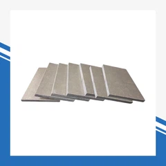
Made of grain-oriented silicon steel laminations to reduce loss and improve efficiency.
Supports the windings and transmits magnetic flux between coils.
2. Windings (Electrical Circuit Part)
High-voltage winding: Connected to the high-voltage side.
Low-voltage winding: Connected to the low-voltage side.
Both windings are insulated from each other and from the core.
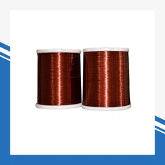
Made of copper or aluminum conductor with high-voltage insulation.
3. Insulation System
Insulating paper, cardboard, oil insulation, and resin materials.
Isolates windings, core, and leads to prevent short circuits and breakdown.
4. Transformer Tank
The outer metal casing that holds the core, windings, and insulation oil.
Provides mechanical protection and structural support.
5. Insulation Oil
Fills the tank to cool and insulate the core and windings.
Extends service life and prevents partial discharge.
6. Cooling System
Radiator / cooling fins to dissipate heat generated during operation.
Ensures stable temperature under rated load.
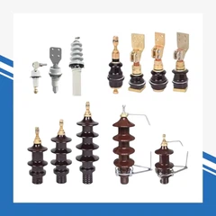
7. Bushings (High-Voltage / Low-Voltage)
Insulated connectors that lead power in and out of the tank.
Isolate live conductors from the grounded tank.
8. Tap Changer
Adjusts voltage ratio by changing winding turns.
Maintains stable output voltage under grid fluctuations.
9. Auxiliary Protection Parts
Conservator / expansion tank: compensates for oil volume change.
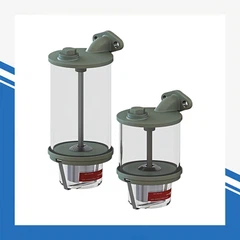
Moisture absorber (breather): keeps air dry and clean.
Pressure relief device: releases internal overpressure.
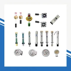
Temperature gauge / oil level indicator: monitors working status.