








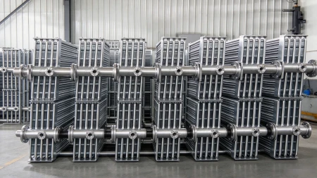
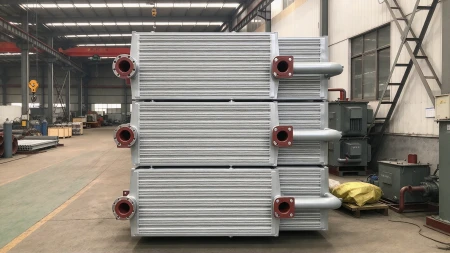
The component that sets a transformer's thermal ceiling
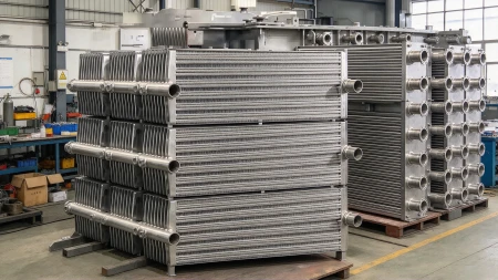
A power transformer's load capacity is limited by how fast it can shed heat. The plate radiator is the component that does that work - a bank of pressed-steel elements through which the hot oil circulates, exposing a large surface to the air so the oil cools and returns to the windings. Get the radiator wrong and the whole transformer is de-rated.
Our plate radiators are built for HV and UHV power transformers, reactors and similar power equipment, manufactured to the Chinese national standard JB/T5347 for transformer plate radiators.
Built to JB/T5347
Every radiator is produced to the dimensional and technical requirements of JB/T5347, then tested for cleanliness, air-tightness and vacuum integrity before it leaves the works. That standard discipline is what allows a radiator to be bolted to a transformer built anywhere and perform as designed.
Model code, decoded
A Weshare radiator designation carries its whole specification:
P - plate radiator.
Connection - C = detachable (flange); G = stationary (direct weld).
Centre distance - distance between the top and bottom oil headers, in mm.
Number of flakes - the number of elements in the group.
Flake width - 520, 480 or 310 mm.
Protection type - TH = wet-tropical environment; TA = tropical environment; no letter = general environment.
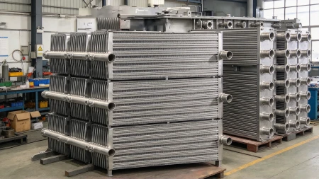
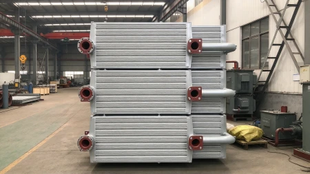
Size
Dimensions & capacity
| Flake width | Centre distance | Flakes per group |
|---|---|---|
| 520 mm | 1,000 – 4,000 mm | 12 – 40 |
| 480 mm | 1,000 – 3,200 mm | 12 – 35 |
| 310 mm | 400 – 1,000 mm | 1 – 12 |
Groups can be combined to suit the transformer's cooling duty, so a single radiator family covers everything from compact distribution units to large UHV transformers.
Two structures: conventional vs gooseneck
| Structure | Centre distance | Typical model | Use |
|---|---|---|---|
| Conventional | Equal (top = bottom) | PC3600-36/520 | Standard tank layouts |
| Gooseneck | Unequal (offset headers) | PC3200(2800)-30(3)/520 | Where the tank outlet positions are offset |
The gooseneck form lets the radiator clear obstructions or match asymmetric tank connections without changing the cooling area.
Two mountings: PG stationary vs PC detachable
| Type | Code | Connection | Description |
|---|---|---|---|
| Stationary | PG | Direct weld, no flange | Welded straight into the transformer-tank outline - permanent, lowest part count |
| Detachable | PC | Flange | Bolted to a flange on the tank - removable for transport or service |


Materials & finishes
Carbon steel - the standard build for general service.
Stainless steel - for corrosive or specialist environments.
Galvanised - for enhanced corrosion resistance in humid or coastal sites.
Each element is pressed with an internal oil channel and welded into a rigid, leak-tight group with lifting rings, connection pipes, connecting lugs and a foot base.
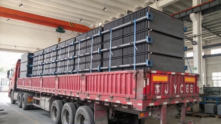
plate radiator
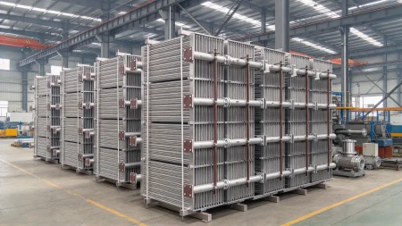
transformer oil radiator
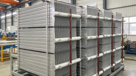
gooseneck radiator
Quality: three factory tests
| Test | Acceptance criterion |
|---|---|
| Cleanliness | Internal rinse with ≥ 35 kV transformer oil |
| Air-tightness | 0.20 MPa held 20 min - no leak, no permanent deformation |
| Vacuum | 133 Pa held 10 min - no permanent deformation |
Selection support
Sizing a radiator bank is a cooling calculation, not a guess. We support customers with the standard empirical method - S1 = 0.75·S1K + S2·nZ/nZ(selected), based on the transformer's oil-tank surface area, required effective cooling area and radiator arrangement coefficient (single-sided 0.9, double-sided 0.85, three-surface 0.8, four-surface 0.75) - or with a full calculation from your transformer data. Where forced cooling is required, DDF air-cooling is specified - for example when transformer capacity reaches 10,000 kVA.
Manufacturing capability
Production runs on a dedicated Tangshan Kaiyuan radiator line: centre distances from 800 to 4,000 mm, an end angle of 3°, rolling-cut and trimmed elements, and capacity up to 300 tonnes per month, supported by a 15-person radiator team.
Applications
HV and UHV power transformers · shunt reactors · converter and furnace transformers · any oil-immersed equipment requiring a dedicated cooling bank.
To quote accurately, we need:
Centre distance and flake width (520 / 480 / 310 mm)
Number of flakes per group, or the required cooling area
Mounting - PG stationary or PC detachable
Structure - conventional or gooseneck (with header offsets)
Material/finish - carbon steel, stainless or galvanised
Environment - general, TA tropical or TH wet-tropical
Hot Tags: plate radiators for power transformers, China plate radiators for power transformers suppliers, transformer bridges, transformer building automation accessories, transformer exporters, transformer industries, transformer modulators, transformer representatives